To make things simple to start with, we shall look at ESPHome. Ideally, we’d like to not use Wifi or any wireless setup, but we want to get things rolling especially when it comes to power. We want to be able to know how much power is available so that we can take action like go and start the engine to charge the batteries up.
We have a few spare Lilygo units about, like the T-Display S3. Featuring the ESP32 S3R8, 16MB flash memory, 1.9″ LCD display, a QWIIC connector and LiPo battery charging.
There is an add-on for Home Assistant called ESPHome Device Builder. One thing to note is that you’ll need to run this in Chrome since Safari does not have USB serial capability. Also, it doesn’t run if the home assistant instance is not secure… so you need to use ESPHome web which runs in the browser and is secure.
We’ve managed to setup the T-Display S3 as an ESPHome device and it appears to be online in the ESPHome plugin. We can also view the logs and it is showing as being connected to the WiFi. But we cannot currently ‘Visit’ the device.
We will try it again but instead of connecting it to the MacBook Pro, we shall connect it directly to the Raspberry Pi. Flashing seemed successful, but the Visit button still does not connect.
Apparently other people have this issue too, we shall look at this in the future if it’s needed.
We found a basic configuration on the ESPHome website https://devices.esphome.io/devices/lilygo-tdisplay-s3/ This enables the display, allows the control of the backlight and can read the two buttons on the device. We edited the yaml file to include the extra parts from the example and installed this on the device. Since the the T-Display is now connected to the WiFi, this update could be done over the air. After a short time, the device rebooted, the display came on and showed a test card. In Home Assistant the device now shows controls for the LCD Backlight and the status of the two buttons.
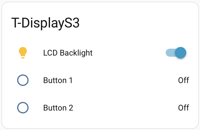
When the buttons are pressed on the device, these values quickly update and are recorded in Home Assistant.
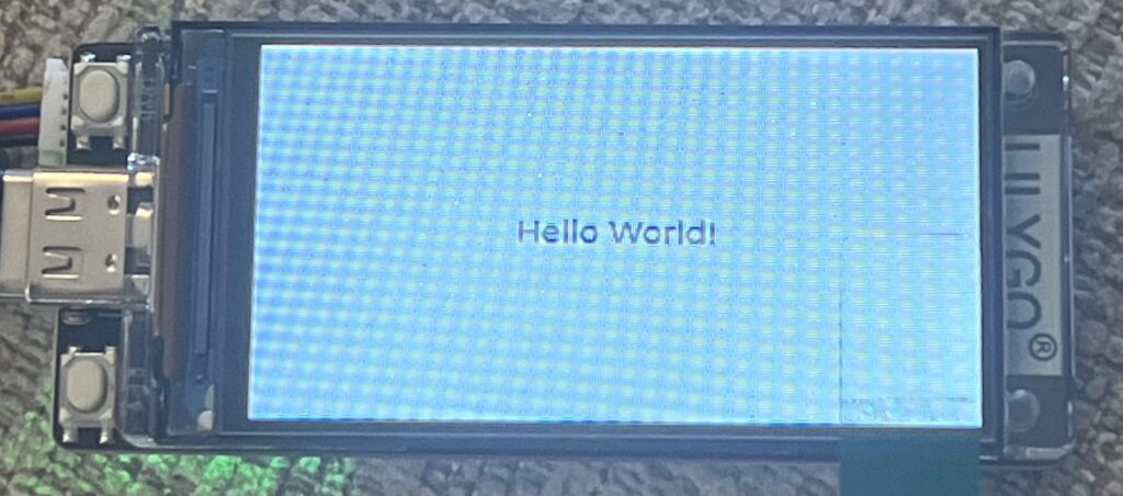
ESPHome can use LVGL (Light and Versatile Graphics Library) to be able to create simple displays. It simply uses YAML to configure the display. so for example:
lvgl:
  widgets:
    - label:
        align: CENTER
        text: 'Hello World!'
simply displays a white screen with Hello World! in the centre
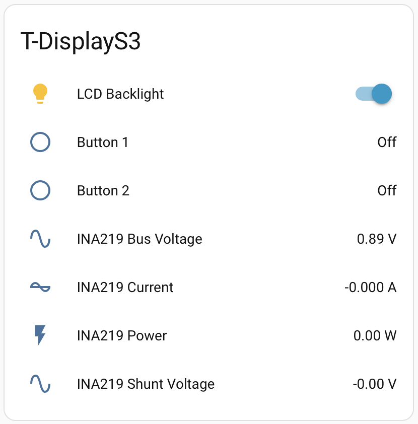
We have an INA219 DC current sensor which connects via the QWIIC connector. A quick google search later and we found the code for the sensor for ESPHome, simple! One thing it does mention is that you need to configure the i2c for the ESPHome device. According to the Lilygo website, i2c is on GPIO 43 and GPIO44.
i2c:
  sda: GPIO43
  scl: GPIO44

sensor:
  - platform: ina219
    address: 0x40
    shunt_resistance: 0.1 ohm
    current:
      name: "INA219 Current"
    power:
      name: "INA219 Power"
    bus_voltage:
      name: "INA219 Bus Voltage"
    shunt_voltage:
      name: "INA219 Shunt Voltage"
    max_voltage: 32.0V
    max_current: 3.2A
    update_interval: 60s
after clicking install and waiting for it to compile, Home Assistant now shows the extra variables:
Initially, we just need to monitor the battery voltage so we could remove the extra Current, Power and Shunt Voltage variables.
i2c:
  sda: GPIO43
  scl: GPIO44

sensor:
  - platform: ina219
    address: 0x40
    shunt_resistance: 0.1 ohm
    bus_voltage:
      name: "INA219 Bus Voltage"
    max_voltage: 32.0V
    update_interval: 60s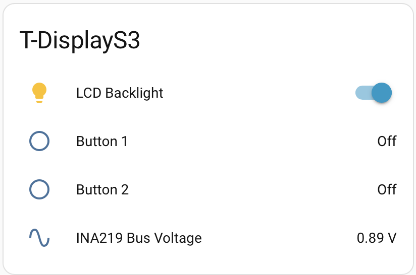
So technically, we can attach this to the leisure batteries to see the voltage. I’m thinking it would be really good to be able to see the current and calculate the power. but this will require a current sensor that is capable of measuring up to 150 amps but still have the granularity to handle a couple of amps.
So we reckon that we could simply remove the shunt resistor from the board we have and then wire in a much larger shunt resistor that will take the current.
Yes we could just go for Victron’s DC Smart Shunt. However, we are planning on putting power sensors all over the boat for the different devices so we can detect if there are any issues and where our power is going, so it would be good to learn how to handle this amount of power.
Now that the Home Assistant setup is on the boat, we tested this ESPHome device but it looks like this INA219 sensor is damaged. This is easily done, if too much current is passed through the shunt resistor, the voltage on the input gets too high and damages the sensor. We shall swap this out and see if that improves.
Bluetooth Proxy
We found that the Raspberry Pi’s Bluetooth has some issues that was causing the Bluetooth integration to crash in Home Assistant so the data from the Victron MPPT solar controller was only being received for about 2 hours, then there would be no data until the integration was reloaded.
We decided to look into an ESPHome Bluetooth proxy which is an ESP32 that connects to the WiFi and relays BLE packets back to Home Assistant.
Leave a Reply