Blog

  • Leisure Batteries

    We have had some issues with our leisure batteries on the boat. Simply put, by the morning, there isn’t enough power in the batteries to start the Webasto heating. It all started when we were in Stratford-upon-avon. It was a really hot day, we had the Ecoflow Wave 3 blasting out cold air and we were moored up in the basin, without the engine on. we noticed that microwave has occasionally beeping and the inverter was clicking, indicating that the leisure battery voltage was very low. we resulted in running the engine, in the basin to power the EcoFlow. But, we also found that the alternator was unable to charge the leisure battery and run the Ecoflow which meant that, that evening, the inverter was struggling and so was the fridge!

    There are five 12 Volt, 100 AmpHours flooded lead acid leisure batteries wired in parallel, totalling 500 AmpHours, or at least they should.

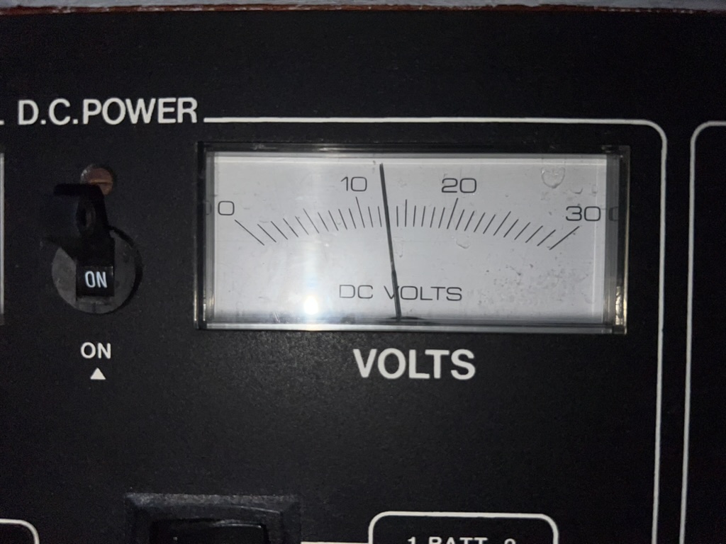
    We have been monitoring the batteries each time we visited it boat via the little DC voltage gauge in the cabin.

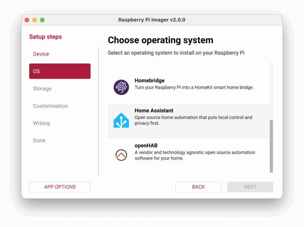
    Daily we would visit the boat, put the engine on and sit there for at least an hour to charge the batteries back up to 14 Volts. But this was getting tedious and we needed a way to remotely monitor the state of the battery. This is where the idea of ESPHome and home assistant came in.

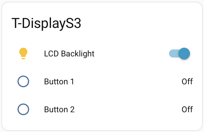
    With home assistant running with Starlink providing the communication link. We created a simple ESPHome device to read the battery voltage. Unfortunately the data recorded from that device is now long gone at the time of writing this post. Needless to say, it was showing that the voltage was dropping too low.

    On the 22nd November installed new batteries, thinking that the old ones that were in the boat, when we bought it, were knackered. We replaced them with new flooded lead acid batteries hoping this will solve the problem, but it’s not that easy.

    In order to generate power, the engine has three alternators. One for the starter battery/bow truster battery via split charger, one for a travel power system (which doesn’t work) and another for the leisure batteries. The leisure batteries can also be charged from the Inverter/charger which is connected to the shoreline connector. The next step was to get solar generation installed. Click here to read about the solar installation

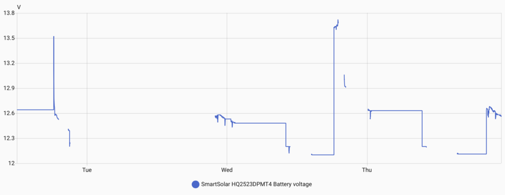
    With the solar installed the controller can read the battery voltage, battery current, solar power and daily yield. This can send this data to home assistant via Bluetooth. This gives us a much more permanent, stable and reliable battery voltage measurement …. once we had got over the Raspberry Pi Bluetooth issues and implemented the ESPHome Bluetooth Proxy.

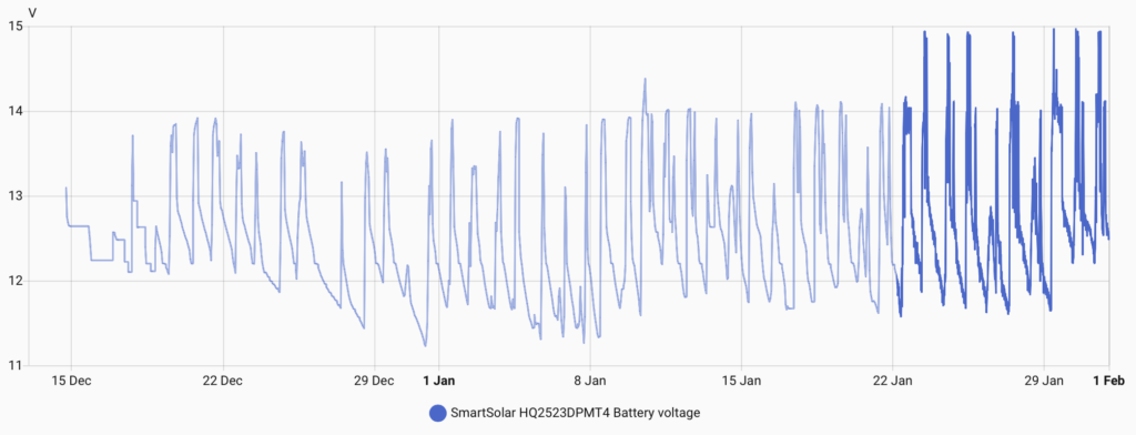
    Now as you can probably recognise, those voltages don’t look great. Ideally, we don’t to dip below 12 Volts.

    This is when we suspected that monitoring the voltage is only half the story. The batteries can get up to 14 Volts, but this doesn’t mean they are fully charged. Therefore, we needed a method of monitoring the current flow into the batteries. Which lead us onto installing a Victron Smart Shunt.

    Smart Shunt

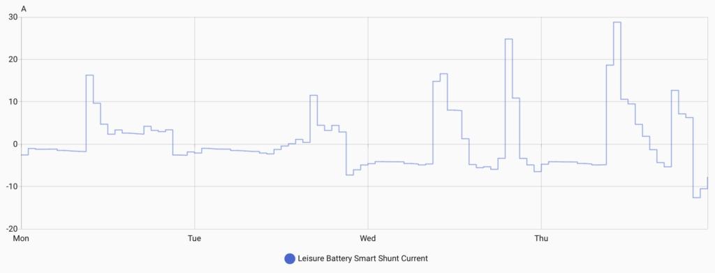
    With this installed we can now see the current flowing in and out of the batteries and sure enough, we could see that they would get to 14 Volts but current would still be flowing into them, indicating that they were not fully charged. It did also showed us that the current went very low, down to 5 Amps, and stayed here until we switched the engine off at 8PM. We also found that on day when the solar kicked in, the solar controller would charge the batteries at 14.7 Volts. When this happened, the current would increase to more than 10 Amps. After reading more into it, flooded lead acid batteries should be charged up to 14.8 Volts, and we found that the regulator on the alternator was fixed at 14 Volts. So the batteries weren’t able to get higher than 14 Volts from the engine alone. This resulted in investing in another piece of Victron tech, the Orion XS DC to DC charger.

    Orion XS

    The DC to DC charger is effectively a buck/boost converter. It will take the input power from the alternator and then ensure the voltage output is maintained by limiting the current on the output. This ensured that the lead acid batteries were being charged at the correct voltage of 14.8 Volts. We did however have to sacrifice one of the leisure batteries as the Orion cannot be only connected to the alternator, it needs a battery to smooth out the alternators output voltage and allow the input stage of the Orion to discharge into the battery once the engine is switched off.

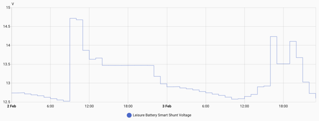
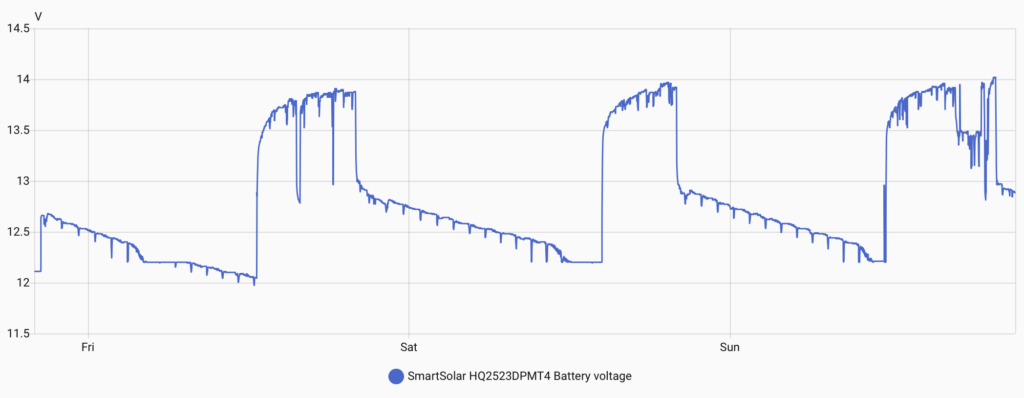
    The graph above shows the battery being charged up to 14.7 Volts (default settings) and then it drops down to 13.47 Volts for the absorption stage of charging.

    We trialled this for a few days and found that the batteries appeared to be charging up properly but we were not seeing much improvement on the capacity.

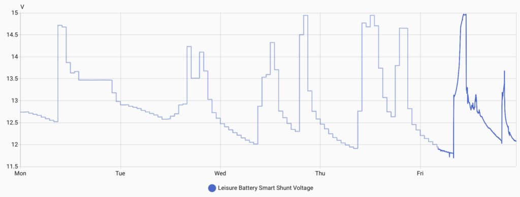
    You can see that by the morning we were still dropping down to below 12 Volts. We were also getting pretty frustrated with having to babysit the boat whilst it was charging the batteries especially when the current was in the single figures.

    We quickly came to the decision that we were wasting our time with flooded lead acid batteries and that we needed to upgrade to Lithium.

    Lithium Batteries

    We had already been evaluating the market of Lithium batteries to figure out the best size in terms of physical size and capacity. We have a limited space envelope in the engine bay to locate the batteries and so it made sense to try and effectively use all of that space. Fogstar do a range of batteries called Drift. We could either opt for a few of the 300 AmpHour batteries or one 628 AmpHour battery. The price difference between these batteries showed that it would be more cost effective per KiloWatt to go for the 628 AmpHour battery of £1,099.99, but it would mean that we would only be able to fit one of them in the engine bay. The 300 AmpHour batteries cost £699.99 but technically, we should be able to fit four of them in the engine bay resulting in a maximum capacity of 1200 AmpHours. We went for two 300Ah batteries.

    Lithium batteries have a much lower resistance, which means the charing current can be much higher than lead acid batteries. Since we will be charging these batteries off the alternator, we need to be able to control the current carefully to make sure we aren’t over charging the batteries and that we aren’t pulling too much current from the alternator. Apparently this is a bigger issue when the engine is just in tick over as the alternator has a fan built in and the speed of the fan is not high enough to keep it cool. Luckily, we had already fitted the Orion XS, so we can carefully control the current. I think I’ll add some temperature sensors to the engine at some point, so the alternator can have it’s own one and we may be able to dial back the current if it is getting too hot. Future project.

    As we said before, we needed one lead acid battery to act as a buffer for the Orion XS. We are thinking of replacing this for a smaller lead acid battery in the future if we need the physical space for more Lithium batteries.

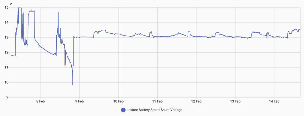
    This graph shows the difference in the voltage between the battery technology. On the 7th of February, we were running on the flooded lead acid batteries. On the 8th, we installed the Lithium batteries. During the installation, we left one of the leisure batteries still attached to allow some power for lights and things. That dip, where the voltage goes down to less than 10 Volts was when we were running the circular saw to create the base for the new batteries to be mounted to. Since the installation day, you can see that the voltage on the batteries are much more stable and above 13 Volts.

    The boat feels very different since installing Lithium batteries. The water pump is more responsive, the lights in the bathroom no longer dip when we flush the toilet, we can run the Webasto heater, and we can even switch the fridge freezer on!

    These new Fogstar batteries even have bluetooth which was very easy to setup on their app and they have a add-on for Home Assistant, so we are now able to see lots of lovely data from each of the batteries, including the all important State of Charge (SoC) and the running time remaining.

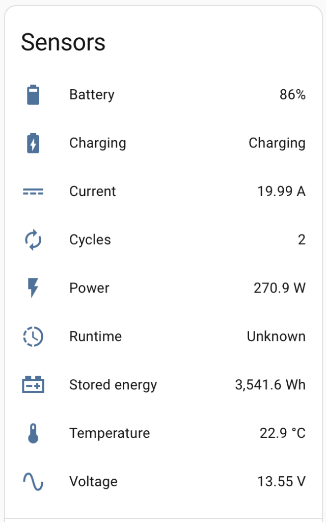
    The runtime in that image is showing unknown as it is currently charging.

  • ESPHome

    To make things simple to start with, we shall look at ESPHome. Ideally, we’d like to not use Wifi or any wireless setup, but we want to get things rolling especially when it comes to power. We want to be able to know how much power is available so that we can take action like go and start the engine to charge the batteries up.

    We have a few spare Lilygo units about, like the T-Display S3. Featuring the ESP32 S3R8, 16MB flash memory, 1.9″ LCD display, a QWIIC connector and LiPo battery charging.

    There is an add-on for Home Assistant called ESPHome Device Builder. One thing to note is that you’ll need to run this in Chrome since Safari does not have USB serial capability. Also, it doesn’t run if the home assistant instance is not secure… so you need to use ESPHome web which runs in the browser and is secure.

    We’ve managed to setup the T-Display S3 as an ESPHome device and it appears to be online in the ESPHome plugin. We can also view the logs and it is showing as being connected to the WiFi. But we cannot currently ‘Visit’ the device.

    We will try it again but instead of connecting it to the MacBook Pro, we shall connect it directly to the Raspberry Pi. Flashing seemed successful, but the Visit button still does not connect.

    Apparently other people have this issue too, we shall look at this in the future if it’s needed.

    We found a basic configuration on the ESPHome website https://devices.esphome.io/devices/lilygo-tdisplay-s3/ This enables the display, allows the control of the backlight and can read the two buttons on the device. We edited the yaml file to include the extra parts from the example and installed this on the device. Since the the T-Display is now connected to the WiFi, this update could be done over the air. After a short time, the device rebooted, the display came on and showed a test card. In Home Assistant the device now shows controls for the LCD Backlight and the status of the two buttons.

    When the buttons are pressed on the device, these values quickly update and are recorded in Home Assistant.

    ESPHome can use LVGL (Light and Versatile Graphics Library) to be able to create simple displays. It simply uses YAML to configure the display. so for example:

    lvgl:
      widgets:
        - label:
            align: CENTER
            text: 'Hello World!'

    simply displays a white screen with Hello World! in the centre

    We have an INA219 DC current sensor which connects via the QWIIC connector. A quick google search later and we found the code for the sensor for ESPHome, simple! One thing it does mention is that you need to configure the i2c for the ESPHome device. According to the Lilygo website, i2c is on GPIO 43 and GPIO44.

    i2c:
      sda: GPIO43
      scl: GPIO44
    
    sensor:
      - platform: ina219
        address: 0x40
        shunt_resistance: 0.1 ohm
        current:
          name: "INA219 Current"
        power:
          name: "INA219 Power"
        bus_voltage:
          name: "INA219 Bus Voltage"
        shunt_voltage:
          name: "INA219 Shunt Voltage"
        max_voltage: 32.0V
        max_current: 3.2A
        update_interval: 60s

    after clicking install and waiting for it to compile, Home Assistant now shows the extra variables:

    Initially, we just need to monitor the battery voltage so we could remove the extra Current, Power and Shunt Voltage variables.

    i2c:
      sda: GPIO43
      scl: GPIO44
    
    sensor:
      - platform: ina219
        address: 0x40
        shunt_resistance: 0.1 ohm
        bus_voltage:
          name: "INA219 Bus Voltage"
        max_voltage: 32.0V
        update_interval: 60s

    So technically, we can attach this to the leisure batteries to see the voltage. I’m thinking it would be really good to be able to see the current and calculate the power. but this will require a current sensor that is capable of measuring up to 150 amps but still have the granularity to handle a couple of amps.

    So we reckon that we could simply remove the shunt resistor from the board we have and then wire in a much larger shunt resistor that will take the current.

    Yes we could just go for Victron’s DC Smart Shunt. However, we are planning on putting power sensors all over the boat for the different devices so we can detect if there are any issues and where our power is going, so it would be good to learn how to handle this amount of power.


    Now that the Home Assistant setup is on the boat, we tested this ESPHome device but it looks like this INA219 sensor is damaged. This is easily done, if too much current is passed through the shunt resistor, the voltage on the input gets too high and damages the sensor. We shall swap this out and see if that improves.


    Bluetooth Proxy

    We found that the Raspberry Pi’s Bluetooth has some issues that was causing the Bluetooth integration to crash in Home Assistant so the data from the Victron MPPT solar controller was only being received for about 2 hours, then there would be no data until the integration was reloaded.

    We decided to look into an ESPHome Bluetooth proxy which is an ESP32 that connects to the WiFi and relays BLE packets back to Home Assistant.

  • Solar

    Procuring Parts

    We want to add solar generation to the boat. We have looked at lots of options and while we don’t really want to completely cover the roof of the boat in solar panels, we think we will need quite a lot of generation.

    We will need solar panels, a way of mounting them to the roof, a solar controller, lots of cabling and cable management accessories and probably like fuses, isolators and loads of other things that we don’t know about.

    There are countless options when it comes to solar installation. We’ve gone for 2x DMEGC 500W panels. The other option was 5x Renogy 200W ShadowFlux panels. The Renogy panels would be better in partial shade due to their ShadowFlux technology but they cost 5x more the standard panels. The DMEGC 500W panels have a Voc (Voltage open circuit) of 44.2 Volts and an Isc (Current short circuit) of 14.04 Amps. These will be wired in parallel so a potential Isc of 28.08 Amps.

    We are going to mount these to the boat using Midsummer Energy tilt mount system. This will allow us to angle the panels more towards the sun. They also have a benefit of having the panels flat but raised from the boat, so we could store things under them like bags of wood.

    The solar controller we’ve chosen is overkill for our initial setup but it will future proof in case we want to add more or add temporary solar panels. The Victron SmartSolar MPPT 250/100 VE.Can can take a Vsc of 245 Volts and a Isc of 70 Amps. Although we have just noticed on the data sheet that the “Nominal PV power, 12V” is 1450W and if more solar is available then it will limit the charging power… But most of the time, the solar panels are not running at full wack. So if we add more panels, it will just mean that the whole system is more sensitive during overcast days. Or we can upgrade to a 24 Volt system which will increase the charging power to 2900W. But this will be an increase of an addition 3x 500W panels, we don’t have the roof space for this, unless we did something special!

    In order to wire the solar panels in parallel, We’ve purchased some MC4 Y-splitters. One of them has 1x plug and 2x sockets and the other has 1x socket and 2x plugs. This will enable a simple waterproof connection.

    We also have some waterproof glands to get the cables from the solar panels into through holes in the roof of the boat into the cabin to connect to the solar controller. We’ve also got Sikaflex adhesive to stick them down and seal them, we shall also use this on the solar panel mounts to ensure moisture does not get into the holes.

    We thought that isolators would be a good idea, it’s not technically required, but if you can imagine, once the panels have light on them, they generate potential. So isolators allow safer connections and for any reason, we can easily disconnect the panels or isolate the controller from the batteries. Better safe than sorry.

    On the subject of safety, we have a Victron Mega 6 way fuse holder. Since the fuses we require are in the hundreds of amps, they need some good secure, low resistance connections and mechanical protection from anything conductive.

    In order to connect all of these things together we’ve got 6mm2 cable for the solar side and 35mm2 for the battery side. There is quite a difference here, but that is because the solar side is higher voltage and lower current than the battery side. Plus with future proofing in mind, 35mm2 is the largest size the Victron MPPT controller can handle. To ensure clean safe connections, we have ring tag crimps for the fuse board, isolators and battery connections. Ferrule crimps for cable ends going into MPPT controller and MC4 crimped connectors for the solar panels.

    Now we’ve just goto to install it all!


    MPPT Controller Installation

    We found a good location for the Victron MPPT solar controller which is just above the current inverter (this may get upgraded in the future). We then made up the cables to connect the controller to the fuse board. This used the 35mm2 cable, an SC35-8 ring tag, a large ferrule crimp, and some red and black heat shrink sleeving. We chose a spot where the fuse board could be fitted and easily accessed. Then we made a short cable to go from the fuse board to the isolator. Same setup except the other end used an SC35-10 ring tag. We then attached the isolator to the inside wall of the cupboard low enough that it can still be accessed but not too close to the fuse board to allow for future connections. Another SC35-10 was used to connect the remaining red 35mm2 cable. The ferruled end was connected to the positive screw terminal of the MPPT controller. The negative cable was a black 35mm2 cable with a ferruled end connected directly into the MPPT controllers negative screw terminal.

    Behind one of the control panels at the stern allowed access to the panel behind the inverter. The two cables from the MPPT controller could run into this area and follow the existing cables to the engine bay. SC35-8 ring tags and heat shrink were added to the ends of the cables and connected to the batteries.

    Switching on the isolator the Victron MPPT controller powered up.

    We linked the Victron MPPT controller to the VictronConnect app. From here we can see the voltage on the battery but it relies on a decent Bluetooth connection. This is where Home Assistant comes in. Luckily there is already a Victron BLE integration. In the VictornConnect app we needed to ensure that “Instant Readout via Bluetooth” is enabled and get the encryption key from the App. In Home Assistant, once the bluetooth on the Pi had recognised the Victron MPPT, we could connect it and enter the encryption key. Home Assistant added it as a device and started collecting the data from the controller. Which also means that, because we have Starlink, we can see the data from anywhere on the Home Assistant app. However, this wasn’t exactly plain sailing as we found that the Raspberry Pi’s Bluetooth would only collect data for about 2 hours and then the Bluetooth Integration would need to be reset, then it would work again for another 2 hours.

    This resulted in us looking into creating an ESPHome Bluetooth Proxy. Check out this post for more details on that. Once we started using it the data was coming through much more frequently.


    Solar Panel Installation

    So the main attraction are the solar panels. These need to be mounted to the roof and as we mentioned earlier, we will be using mounts that allow the panels to be tilted towards the sun. The mounts attach to the boat in the centre with two brackets, one for each side, with a rubber pad and 2x M8 bolts. We marked, drilled, tapped the roof and mounted the brackets.

    The arms are basically a square aluminium tube with another square tube inside it that has slots running along its length. Two screws lock the centre tube in place, when you want to tilt the panels, the screws are loosened, the centre tube extends out and the arms get longer. The arms are attached to two rails which sit under the panels and clamps at either end hold the panels in place.


    Solar Panel Cabling

    Just like the connection to the batteries, we used an isolator and connected to the fuse board before connecting to the MPPT controller. The cables are routed along the gunnel into the bedroom, through the wardrobes and up to the ceiling where they punch through the roof. To prevent any leaks from the roof, a two port cable gland is used and stuck onto the roof with Sikaflex 522 adhesive. They are then terminated with MC4 connectors, which are crimped onto the end of the wires with a special MC4 crimper.

  • Home Assistant Setup

    We have chosen Home Assistant as the host for the smart upgrade for the boat. We use Home Assistant at home to manage things like the solar and EV car charging. At home, this is hosted on a HP rack server, of the boat, we will go with a simple Raspberry Pi 5 8GB. We also opted for HAOS to enable simple plugin additions. On the home server, I setup portainer and had Home Assistant running in a docker container. Which is great for custom installs, but not really needed on the boat install yet.

    Since the boat will using Starlink for internet access it makes sense that we utilise the Nebu Casa cloud service to be able to access the Home Assistant remotely. I’m not sure how Starlink handles the public IP and with this, I don’t need to care, plus we get backups and voice assistant connection if we want to add that in the future.

    Setup was a breeze, using the Raspberry Pi Imager, HAOS is built into this in the ‘other OS’ section.

    We plugged the Pi into home network via ethernet to start with to set it up. The Starlink is on the boat, so for now I’ve also tethered it to my phone. Once we move it over to the boat, we will attach it to the Starlink. At some point, the Starlink will be ethernet connected to the network on the boat, but this needs to be built first. Future post. We’ve also set it up on the companion app on our iPhones which was super simple thanks to the Nabu Casa cloud service.

    As we’ve said in ‘The Boat Systems’ post, power is a limited resource. So we are planning a sort of UPS (Uninterruptible Power Supply) which will power the Raspberry Pi and the Starlink. We have chosen the Anker Solix C200 power bank to act as the UPS as it has plenty of USB-PD ports but also a DC input which can vary from 11V to 28V. I am going to look into how I can interface with this in Home Assistant.

    To enable the installation of extra add-ons that are part of the community store, We have installed HACS onto Home Assistant using the instructions found here. To use HACS, you’ll also need a GitHub account which we have.


    So the Home Assistant setup is now on the boat. However, we got a USB-C adapter for the Starlink mini which would allow us to power it from the Anker power bank. But it does not appear to be working correctly. One option is that I can move the power from the power bank to a USB-C AC adapter to see if it is the power bank, or just power it from the normal Starlink AC adapter.

  • The Boat’s Systems

    We have a 60′ narrowboat which (in my opinion) is asking for a tech upgrade. There’s plenty of systems on board that have opportunities to be upgraded with monitoring and control tech. Some environment monitoring would be good to have as humidity levels on a boat can be all over the place, which can easily lead to damp areas.

    The boat systems currently include (from back to front (stern to bow)),

    • Diesel Engine
    • Diesel heating system for hot water and heating
    • Leisure Batteries
    • AC power
    • Toilet tank
    • Bathroom stuff
    • Lighting
    • Gas oven and hob
    • Fridge freezer
    • Washing machine
    • Kitchen sink
    • Fresh water pump and tank
    • Air source heat pump
    • Bow thruster
    • Navigation lights and horn
    • Starlink

    So I’d love to try and add some smarts to these systems to be able to monitor them and alert if anything is untoward. I’d also like to add solar and CCTV

    Most narrowboats we have seen have some smart electrical power systems and maybe a remote start for the heating system. These usually comprise of a Victron power system which can be accessed through their app. This would do everything from battery charging and maintenance, solar control and inverting the DC to AC for mains power. For the remote heating system, Webasto (who make our diesel heater) have a GSM module that can be attached to the heater to remotely control it. This relies on a subscription to Webasto’s service, which at the time of writing is €34.99 a year.

    So I think the plan is going to be to host a home assistant instance and lots sensors to monitor all the things. Then we can setup automations and alerts with remote control and monitoring. But we need to be conscious that this setup will require power, which is a limited resource on the boat.

  • Setting up the website

    I wanted to setup a website to document my tech adventures. So here we are. It needs a good bit of jazzing up, not too jazzy, but not WordPress basic. For now I think I’ll get some content on here and worry about aesthetics later.

    I want somewhere where I can document what I’ve done, how I did it, why I did it, how I’m getting on with it and what’s next. There has been plenty of times I’ve made something or implemented something, but then I can’t remember how I did it, or why. Hopefully, this will help and maybe help anyone who reads it. If I’m lucky enough to get a comment on how someone else has done a similar thing, then that would be amazing.