Procuring Parts
We want to add solar generation to the boat. We have looked at lots of options and while we don’t really want to completely cover the roof of the boat in solar panels, we think we will need quite a lot of generation.
We will need solar panels, a way of mounting them to the roof, a solar controller, lots of cabling and cable management accessories and probably like fuses, isolators and loads of other things that we don’t know about.
There are countless options when it comes to solar installation. We’ve gone for 2x DMEGC 500W panels. The other option was 5x Renogy 200W ShadowFlux panels. The Renogy panels would be better in partial shade due to their ShadowFlux technology but they cost 5x more the standard panels. The DMEGC 500W panels have a Voc (Voltage open circuit) of 44.2 Volts and an Isc (Current short circuit) of 14.04 Amps. These will be wired in parallel so a potential Isc of 28.08 Amps.
We are going to mount these to the boat using Midsummer Energy tilt mount system. This will allow us to angle the panels more towards the sun. They also have a benefit of having the panels flat but raised from the boat, so we could store things under them like bags of wood.
The solar controller we’ve chosen is overkill for our initial setup but it will future proof in case we want to add more or add temporary solar panels. The Victron SmartSolar MPPT 250/100 VE.Can can take a Vsc of 245 Volts and a Isc of 70 Amps. Although we have just noticed on the data sheet that the “Nominal PV power, 12V” is 1450W and if more solar is available then it will limit the charging power… But most of the time, the solar panels are not running at full wack. So if we add more panels, it will just mean that the whole system is more sensitive during overcast days. Or we can upgrade to a 24 Volt system which will increase the charging power to 2900W. But this will be an increase of an addition 3x 500W panels, we don’t have the roof space for this, unless we did something special!
In order to wire the solar panels in parallel, We’ve purchased some MC4 Y-splitters. One of them has 1x plug and 2x sockets and the other has 1x socket and 2x plugs. This will enable a simple waterproof connection.
We also have some waterproof glands to get the cables from the solar panels into through holes in the roof of the boat into the cabin to connect to the solar controller. We’ve also got Sikaflex adhesive to stick them down and seal them, we shall also use this on the solar panel mounts to ensure moisture does not get into the holes.
We thought that isolators would be a good idea, it’s not technically required, but if you can imagine, once the panels have light on them, they generate potential. So isolators allow safer connections and for any reason, we can easily disconnect the panels or isolate the controller from the batteries. Better safe than sorry.
On the subject of safety, we have a Victron Mega 6 way fuse holder. Since the fuses we require are in the hundreds of amps, they need some good secure, low resistance connections and mechanical protection from anything conductive.
In order to connect all of these things together we’ve got 6mm2 cable for the solar side and 35mm2 for the battery side. There is quite a difference here, but that is because the solar side is higher voltage and lower current than the battery side. Plus with future proofing in mind, 35mm2 is the largest size the Victron MPPT controller can handle. To ensure clean safe connections, we have ring tag crimps for the fuse board, isolators and battery connections. Ferrule crimps for cable ends going into MPPT controller and MC4 crimped connectors for the solar panels.
Now we’ve just goto to install it all!
MPPT Controller Installation
We found a good location for the Victron MPPT solar controller which is just above the current inverter (this may get upgraded in the future). We then made up the cables to connect the controller to the fuse board. This used the 35mm2 cable, an SC35-8 ring tag, a large ferrule crimp, and some red and black heat shrink sleeving. We chose a spot where the fuse board could be fitted and easily accessed. Then we made a short cable to go from the fuse board to the isolator. Same setup except the other end used an SC35-10 ring tag. We then attached the isolator to the inside wall of the cupboard low enough that it can still be accessed but not too close to the fuse board to allow for future connections. Another SC35-10 was used to connect the remaining red 35mm2 cable. The ferruled end was connected to the positive screw terminal of the MPPT controller. The negative cable was a black 35mm2 cable with a ferruled end connected directly into the MPPT controllers negative screw terminal.
Behind one of the control panels at the stern allowed access to the panel behind the inverter. The two cables from the MPPT controller could run into this area and follow the existing cables to the engine bay. SC35-8 ring tags and heat shrink were added to the ends of the cables and connected to the batteries.
Switching on the isolator the Victron MPPT controller powered up.
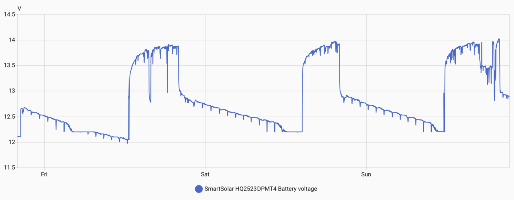
We linked the Victron MPPT controller to the VictronConnect app. From here we can see the voltage on the battery but it relies on a decent Bluetooth connection. This is where Home Assistant comes in. Luckily there is already a Victron BLE integration. In the VictornConnect app we needed to ensure that “Instant Readout via Bluetooth” is enabled and get the encryption key from the App. In Home Assistant, once the bluetooth on the Pi had recognised the Victron MPPT, we could connect it and enter the encryption key. Home Assistant added it as a device and started collecting the data from the controller. Which also means that, because we have Starlink, we can see the data from anywhere on the Home Assistant app. However, this wasn’t exactly plain sailing as we found that the Raspberry Pi’s Bluetooth would only collect data for about 2 hours and then the Bluetooth Integration would need to be reset, then it would work again for another 2 hours.
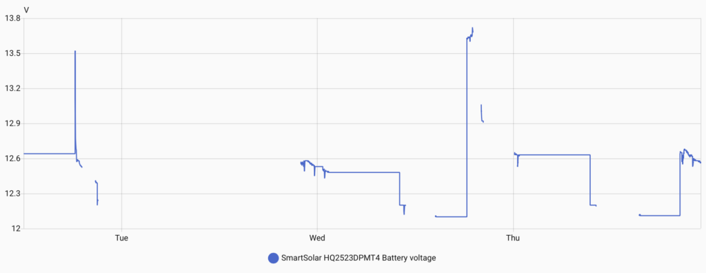
This resulted in us looking into creating an ESPHome Bluetooth Proxy. Check out this post for more details on that. Once we started using it the data was coming through much more frequently.
Solar Panel Installation
So the main attraction are the solar panels. These need to be mounted to the roof and as we mentioned earlier, we will be using mounts that allow the panels to be tilted towards the sun. The mounts attach to the boat in the centre with two brackets, one for each side, with a rubber pad and 2x M8 bolts. We marked, drilled, tapped the roof and mounted the brackets.
The arms are basically a square aluminium tube with another square tube inside it that has slots running along its length. Two screws lock the centre tube in place, when you want to tilt the panels, the screws are loosened, the centre tube extends out and the arms get longer. The arms are attached to two rails which sit under the panels and clamps at either end hold the panels in place.
Solar Panel Cabling
Just like the connection to the batteries, we used an isolator and connected to the fuse board before connecting to the MPPT controller. The cables are routed along the gunnel into the bedroom, through the wardrobes and up to the ceiling where they punch through the roof. To prevent any leaks from the roof, a two port cable gland is used and stuck onto the roof with Sikaflex 522 adhesive. They are then terminated with MC4 connectors, which are crimped onto the end of the wires with a special MC4 crimper.
Leave a Reply